I have the experience, equipment, time and inclination to drill down into the performance of various motors that have been used in turntables from the 1960’/70’s onwards to the current trends. This is not comprehensive but covers several of the more prolific types as well as some interesting ones. The tests will drill down into how the motors actually behave in terms of whether the speed of rotation (aka torque ripple), is in fact constant, which clearly is what a turntable requires, how the power supply affects this, what ‘slip’ there is under small loads and some other interesting parameters.
The better a motor behaves, the less has to be done to correct issues – for example, less mass has to be added to compensate for poor motor behaviour. Whilst motor performance does not singularly define how a turntable will sound overall, it has an influence on design, especially high end units, idler wheel etc.
The motor is the heartbeat of a turntable…..
Parameters:-
Rotational speed – ideally absolutely constant with no ‘cogging’ i.e. small changes in speed that are a function of creating a smooth rotating magnetic field by energising windings. Also described as torque ripple – a torque variation which results in a change in rotor speed. Normally this is measured under load, but given the turntable application where the drive torque to keep the platter spinning is on average low, we will measure rotor speed variation under no load and under slight load to simulate stylus drag when the slip tests are performed.
Slip – slowing down under load, even momentarily. Many motors need to slow down in order to generate more torque to maintain an ‘overall’ constant speed. For a turntable this should be small.
Stray flux/end float – Not all the magnetic field generated goes into rotation – some flux generates a force along the axis of the motor, the ‘Z-axis’, resulting in the shaft potentially moving up/down e.g vibrating albeit in an axis that may have little direct influence on platter motion.
Inertia – This is fundamental. Any energy required by the stylus under load/playing needs to be provided by the drive. If slip (or feedback loop) alone is the mechanism then this allows momentary slowing before correction. If the motor has inertia then this energy store is immediately available. A medium sized flywheel motor at 1500rpm has as much stored energy as a 43Kg (95lb) platter…..(~2.9 Joules)
Setup
The initial principal adopted for rotational speed and stray flux is to use an accelerometer to measure the stator rotational acceleration which is a result of the rotor not moving at a constant speed. This is a second order effect but is sufficiently coupled (Newtons 3rd Law – action and reaction are equal and opposite), thus revealing of variation in rotor speed/torque ripple and is limited to comparative behaviour (particularly tuning a specific motor and comparing motors with similar rotor and stator mass/moment of inertia). What this approach cannot provide is the speed variation of the rotor – for example a small/light rotor with a large speed variation would be similar to a larger rotor with less speed variation. Also, the measurement is still a mix of the 2nd order speed effects and 1st order imbalance components which will require separating where possible, if the frequencies allow. The setup would also be reproducible, if needed. Using an accelerometer/spectrum analyser is not new – in 2014 I posted Lenco and other motor plots on Lenco Heaven and I have seen a similar setup since in the Netherlands. Combining with a direct measurement of angular speed variation will provide new insights….
This approach will be validated as the tests for slip get underway as these will use a direct on shaft encoder to correlate the results and directly measure dynamic speed variation during one rotation of the motor. A custom eddy current brake will be used to apply a known, instant load.
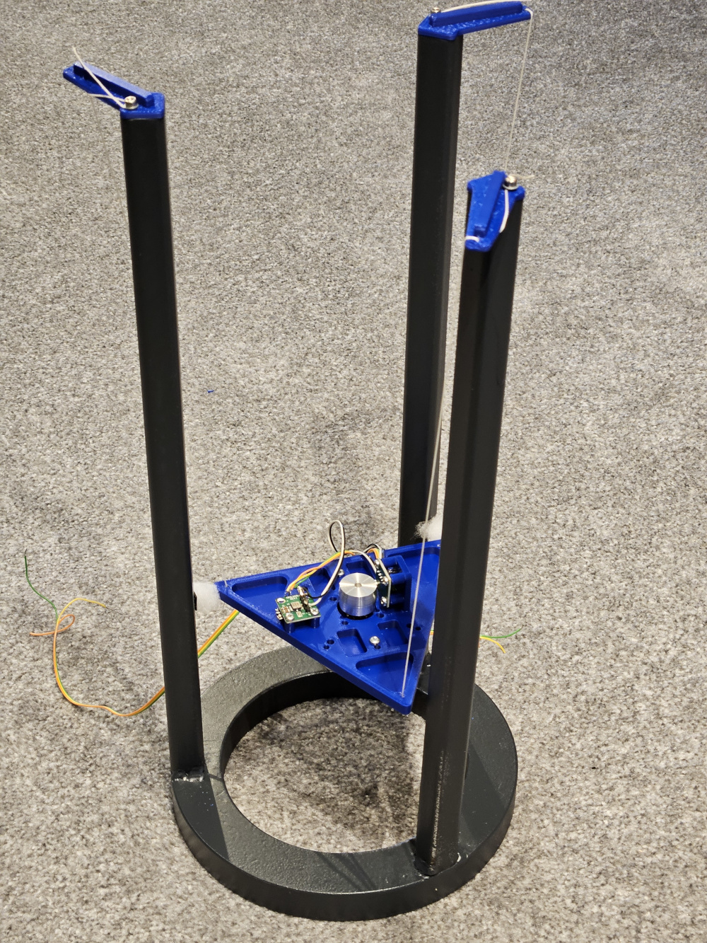
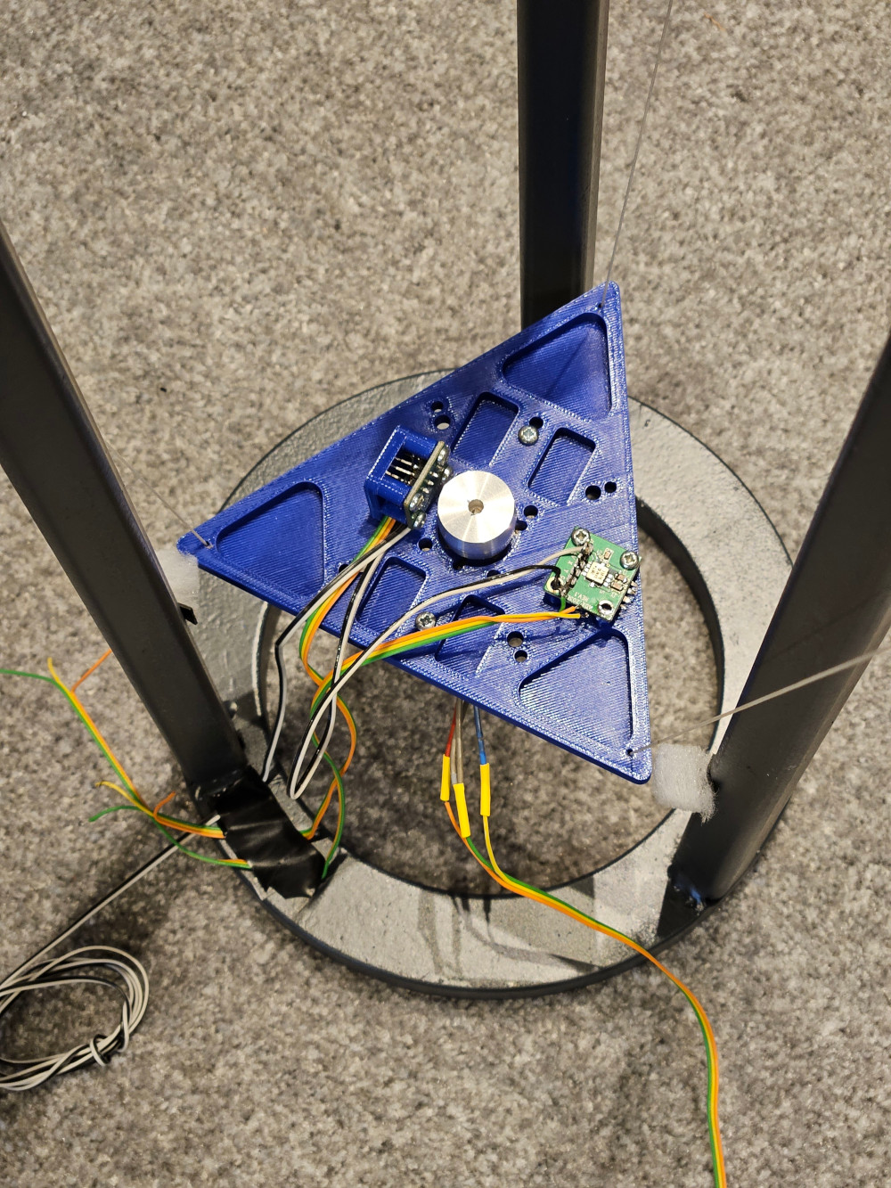
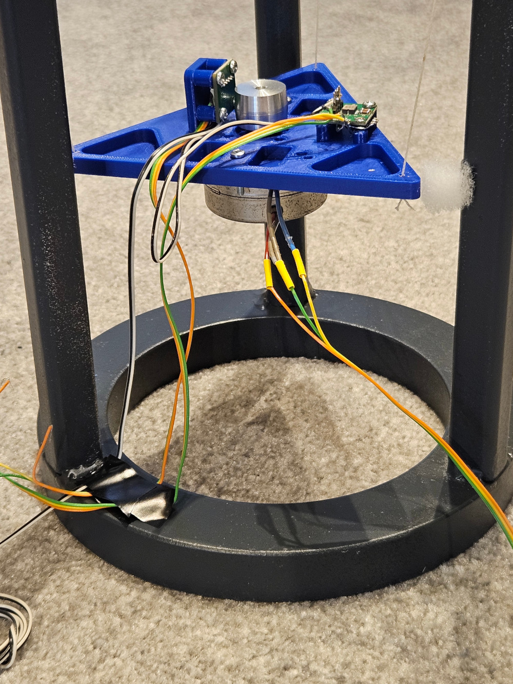
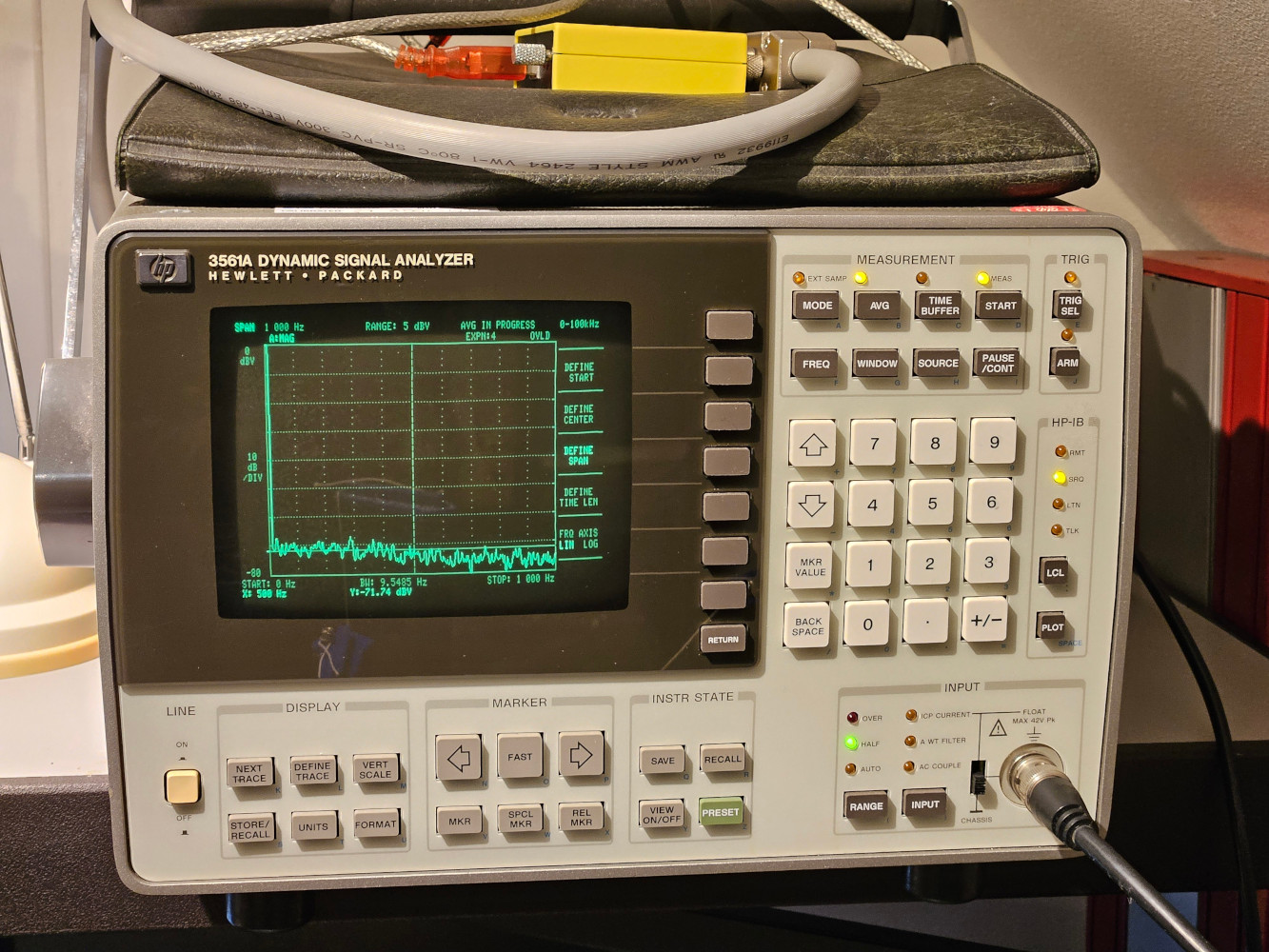
A universal lightweight 3D printed mounting plate (<50gram) , suspended from a rigid platform, that can accommodate all but one of the current motors and uses buffered accelerometers to measure rotational vibration (as a tangent) and vertical Z-axis vibration (output filters set to -3dB @ 500Hz). The analyser is an HP3561A with IEEE488 data transfer to a PC with plotter emulator S/W. Clearly there is some mass in the setup which will reduce the measured signal slightly, however as the tests are comparative this is not a concern as it is the same for all motors (except the Lenco). The spectrum plots show signals at the drive frequency and the harmonics of this as well as rotor imbalance. Any rotor imbalance component will be at a lower frequency e.g. 250rpm = 4Hz, 750rpm 12Hz and not affected by the drive method. The vibration peaks are at 25Hz and 50Hz depending on motor and their harmonics – typically even order. For brushed DC motors the number of commutator segments determine the potential cogging for the ‘open loop’ test – 11 for the Maxon brushed unit, so the frequencies of interest at 750rpm will be 138, 276Hz etc. More on what happens in ‘closed loop’ later where the feedback drive signals in the form of changing current are part of the behaviour – a change in current is a change in flux and thus speed. There are claims of ‘perfect’ DC control but this needs scrutiny…..
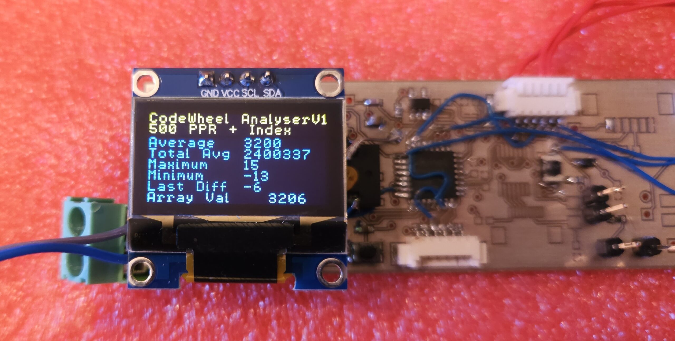
The rig has been updated to include a 500 pulse per rev encoder, precision mounted using alignment tools, on the motor shaft. This now allows absolute rotational speed measurement. A microcontroller running at 20MHz and using it’s externally triggered, 1 cycle (50nS)16 bit timer, is used to capture the precise time between each of the 500 encoder pulses. At 750rpm 3200 counts occur and at 250rpm 9600 counts for each 1/500th of a turn – > 1.6 million per rev. This enables a precision of 0.03% and 0.01% respectively (-66dB and -72dB). It is synchronised to the encoder index pulse so repeated measurements can be aligned if needed. Some basic computation is run by the microcontroller to show an instant view of the data with the whole data set being uploaded to a PC via a serial link.
.
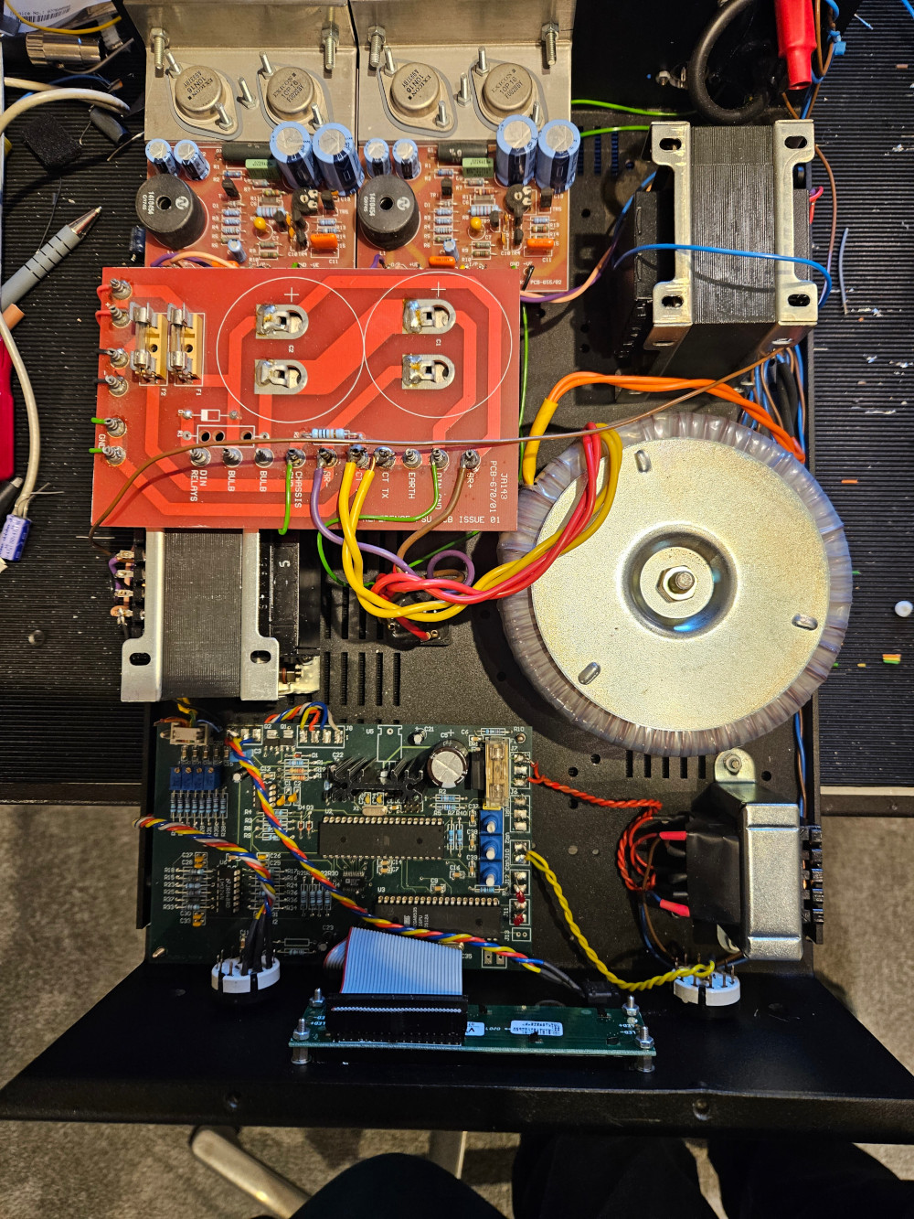
Various motor drives are used – from mains AC, to very low distortion synthesised AC (e.g. <-80dB) (which is better than a Valhalla in terms of harmonic distortion and the known crossover/bias error) to split phase where the start/run phase is finely adjustable to suit the electro magnetic properties of the motor. Back in 2004 I developed adjustable phase controllers for Audio Note and Avid (one programmable and one based on logic gates), and have recently evolved the platform to be even more finely adjustable and accurate. This is a significant investment, but it provides a custom, fully synthesisable (pure sine, sine + distortion, sine + step etc.), low distortion, precision phase adjustable, independent multiphase output controller board. The BLDC ‘types’ are driven from a Maxon ESCON 50/5 controller for now, however we will implement a precision true analog sine wave drive for the fact that the different configuration of ‘BLDC’ motor – a PMSM (permanent magnet synchronous motor) and the drive requirements change for this.
.
There are some summaries below – for complete results of the 11 motors tested to date, scroll down to the dedicated motor links
Summary – Synchronous Philips MB12 type v. Papst B112
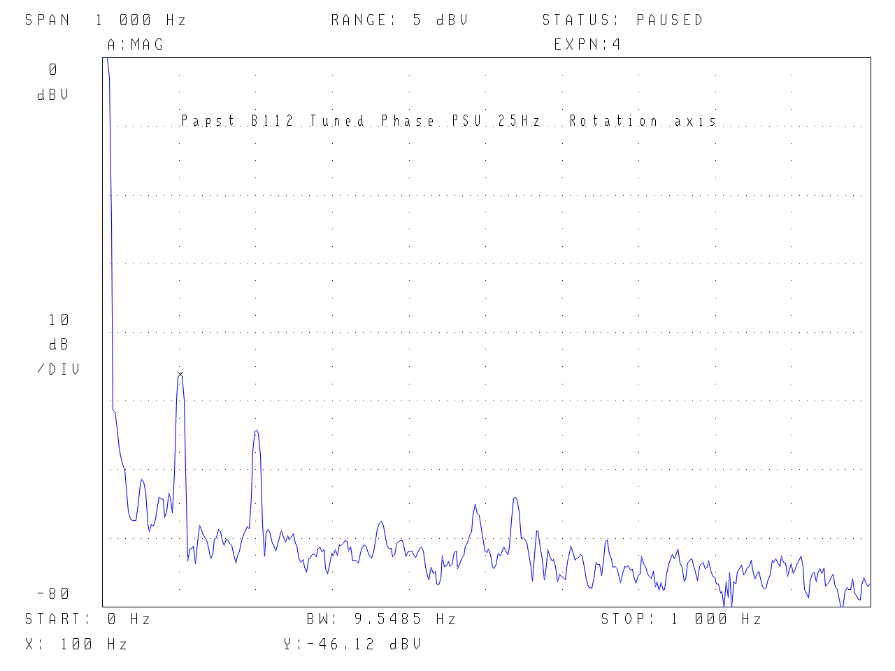
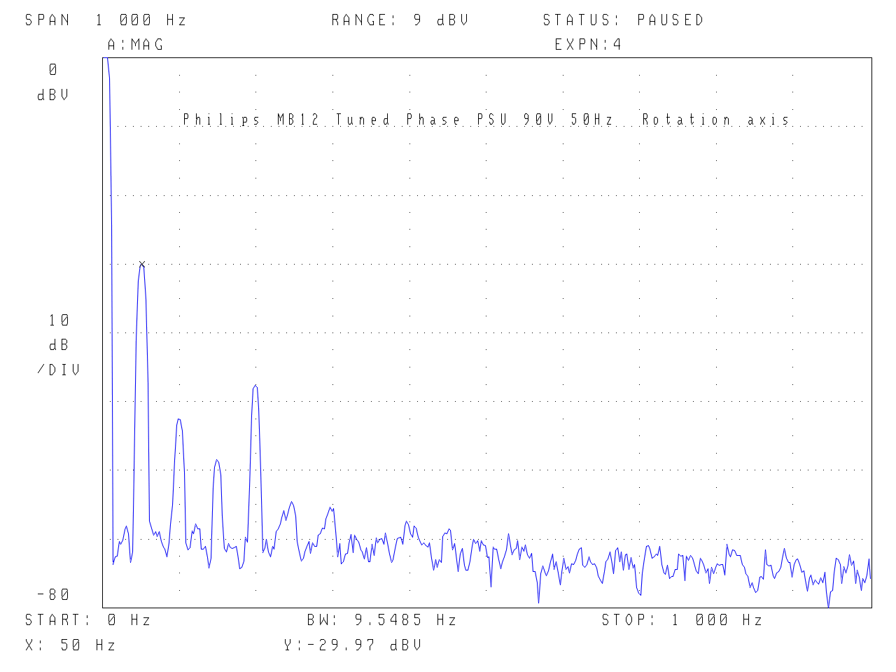
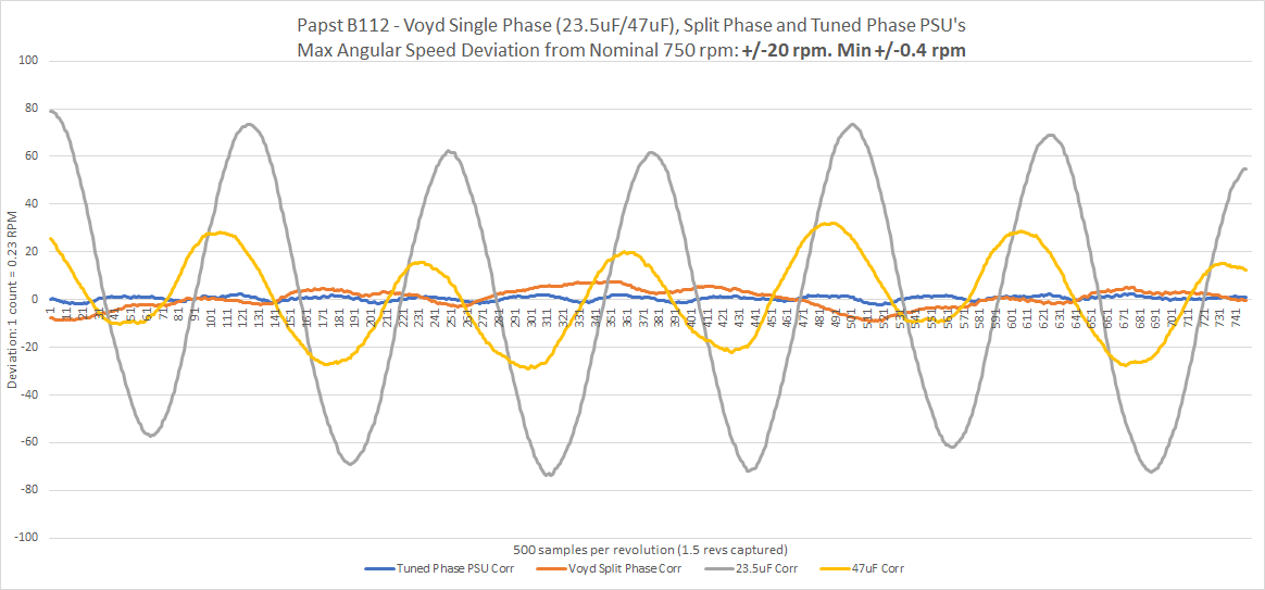
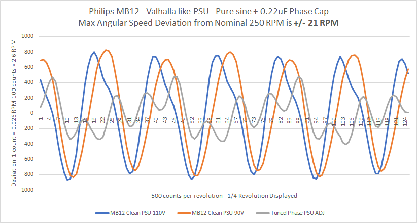
The widely used Philips/Airpax synchronous motor (Linn etc) shows vibration when hand held (regardless of power supply) and a simple experiment reveals that, when some mass is coupled to the motor housing e.g. the top plate/plinth, this drops away, however, DON’T BE FOOLED – this has not made the angular speed constant, all it has done is to hide the apparent pulsing/cogging – the shaft is still rotating at a non-constant speed… 40 years ago I recall it was about £8 (in a £600 turntable), for £12 you could get the Papst B112. The Papst B112 is not a happy bunny when driven from mains (via a transformer) however it improves dramatically with phase control whereas the Philips MB12 just swaps modes…. With control of the phase angle and voltages it is hard by hand to tell the Papst B112 is even rotating with just a 50gram mounting plate…. The recent angular speed measurements really reveal what is going on – the Papst B112 with a Voyd Split Phase PSU has +/- 1.9rpm whereas the Philips MB12 (with a pure sine wave PSU) has +/-21rpm of speed variation within a revolution!
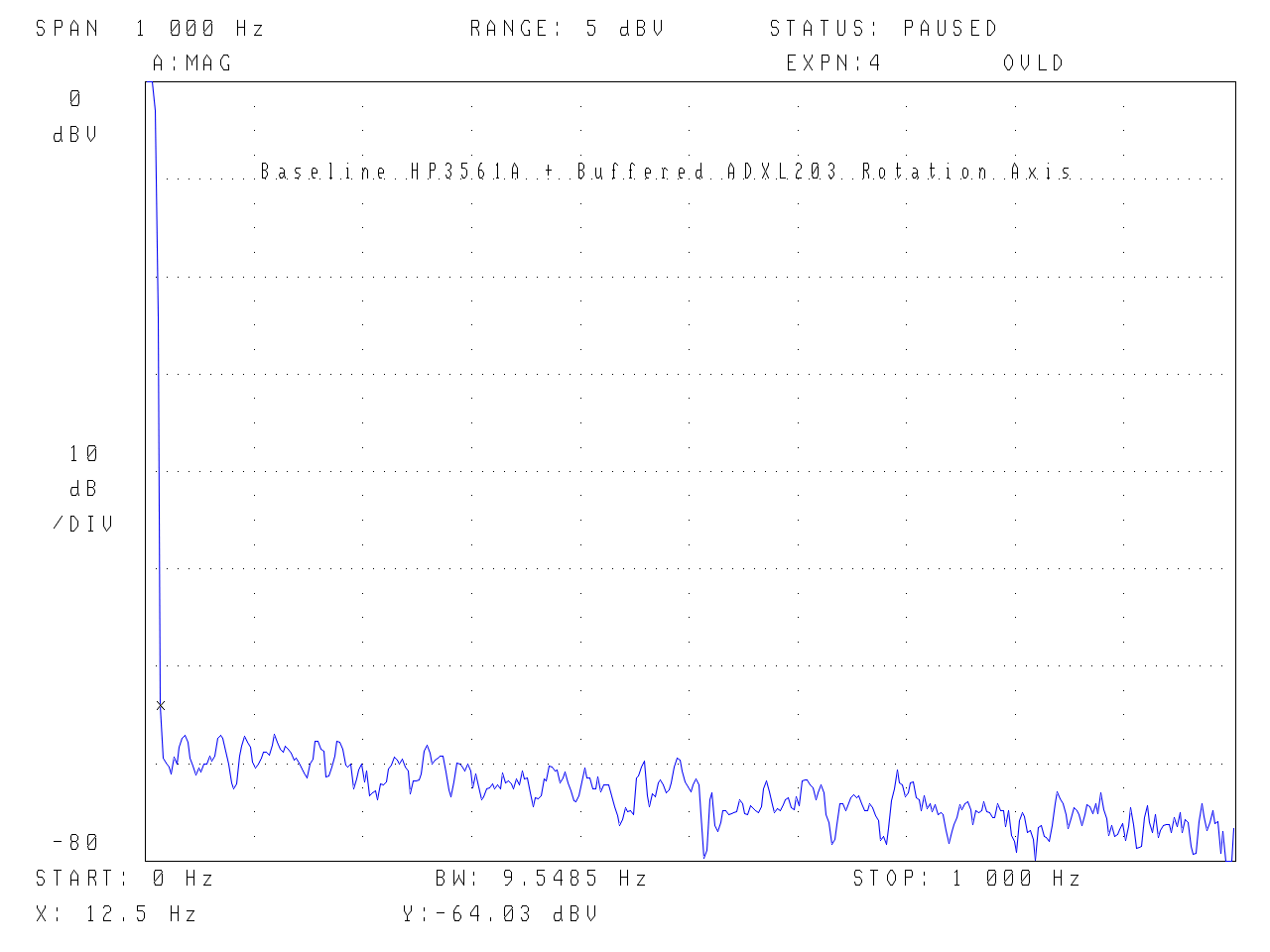
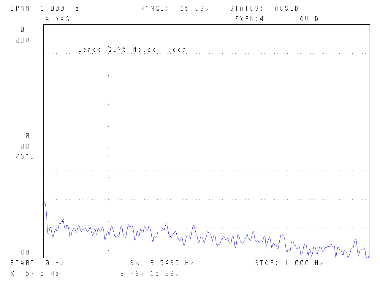
The accelerometer and now absolute angular speed plots below are a summary – Papst B112 left/first, Philips MB12 middle/2nd and baseline is on the right/3rd image and the first plot of absolute shaft speed for the Papst B112 with different power supplies is 4th. Particularly at the lower end of the spectrum on the left of the first plot, the Papst is over 30dB better than the Philips at 50Hz (half the analyser 100Hz grid) – and this is what you can instantly feel as ‘cogging’ AND is now correlated with the absolute shaft speed measurements. Remember, the accelerometer plots are an indicator of speed variation/torque ripple during a revolution – the lower the frequency the more likely it will be transmitted through the belt to the platter & also create small lateral disturbance on the suspension… In terms of getting an absolute measure of speed variation, the shaft encoder plots have to be used as the accelerometer plots include parameters such as moment of inertia/radius of gyration, motor mass etc. The absolute shaft speed plots for the B112 are unequivocal – the better the supply the lower the speed ripple. The best result of 0.46rpm deviation per revolution is remarkably better than the 24 pole Philips MB12 with typically 21rpm as well as the early single phase Voyd power supplies for the Papst B112…..
Summary – DC (brushed)
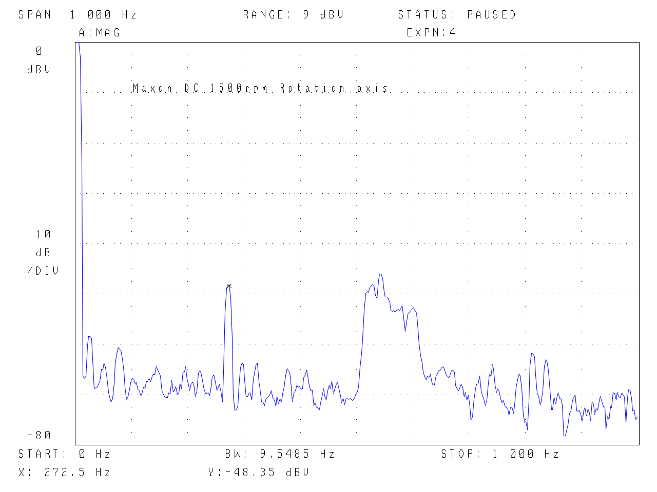
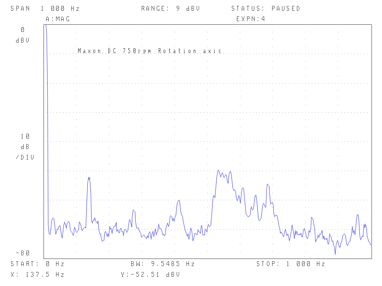
On the face of it this should offer smooth rotation as this Maxon design has no iron in the rotor to ‘detent’ with the permanent magnet stator. However it has a commutator which rotates the field and the tests show that this process is not perfectly smooth – it steps from one commutator segment to the next…
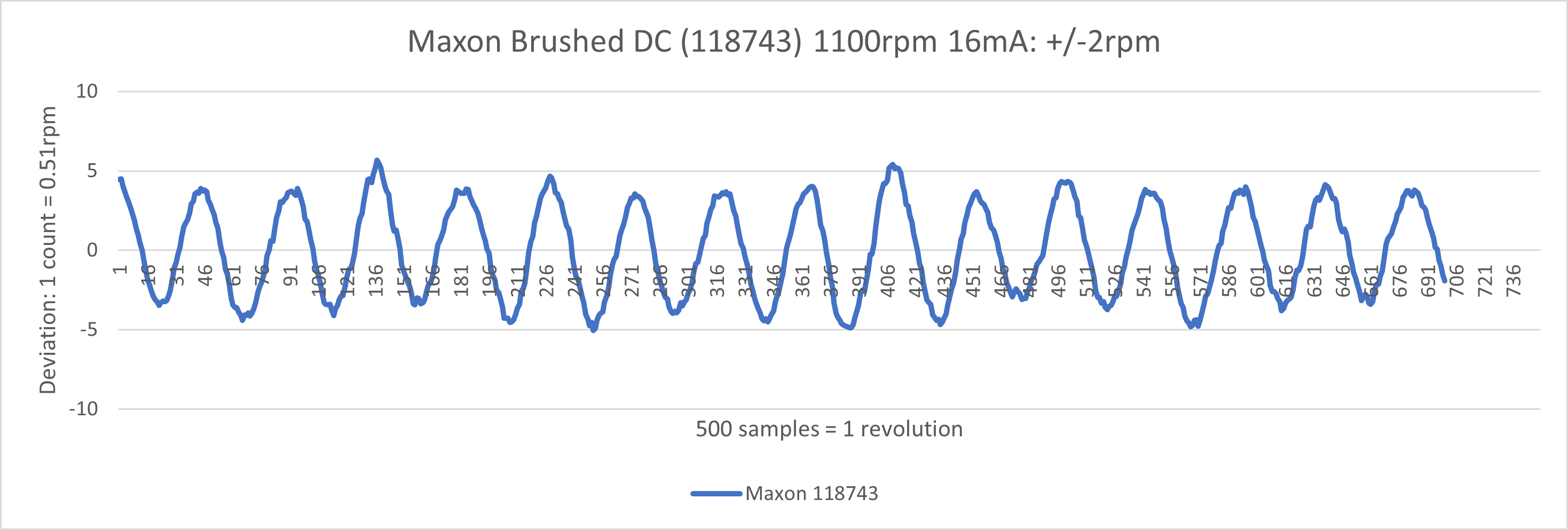
The first spike at 276/138Hz (1500 & 750rpm) for the rotation axis is the 11 commutator segment frequency. Not sure what the large envelope above/around 500Hz is – possibly bearing noise as it is a ball bearing motor. Whilst the plots appear to be comparable to the best Papst B112, the rotor diameter is much smaller (less mass and radius of gyration) thus for it to create similar amplitude signals to the Papst B112, this would imply actual speed variation is higher. Hence the need for direct on shaft speed measurement to directly measure the torque ripple… This has now been added and is +/-2rpm.
Maybe it should not be so surprising that the commutator frequency is so clearly present. When factored in to closed loop control, to have a controller bandwidth that can compensate for this would then imply that there would likely be a lot of correction happening in the control loop. If a low frequency, integrating approach was adopted to maintain 33rpm after gearing of pulley to platter diameter and mass then it would not correct for this higher frequency component. It does not seem unfair to say that this might be why DC motors have not been a slam dunk over other types…. Yes, depending on control loop it is possible for better than a poor synchronous motor, however the Papst B112 with full phase adjustment and significantly larger moment of inertia has 1/4 of the speed variation with 500 times the stored rotational energy….
.
.
Summary – Brushless DC (BLDC) TBD – trapezoidal drive?
Summary – Permanent Magnet Synchronous Motor (PMSM) TBD – sinewave drive
I have a first pass at a true analog sinewave drive design, but in doing this is has highlighted the fact that BLDC/PMSM are still DC motors that just happen to be ‘synchronised’ to the electronic commutation. What this critically misses describing is the fact that under load they will behave just like a DC motor and slow down in order to deliver torque. It is the same mechanism as a brushed DC motor – the speed reduces under load, there is less back emf and thus more current flows from the fixed drive voltage that in turn provides more torque to counter the load. The synchronisation occurs at nominal 3 phase, 120degree/# pole pair intervals if Hall Sensors are used and so provide sparse index points e.g. 15 degrees for a 4 pole pair configuration, which inhibits precision speed control.
Summary – XXXX Synchronous Motor – from the 1960’s…
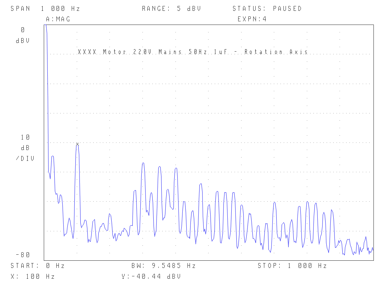
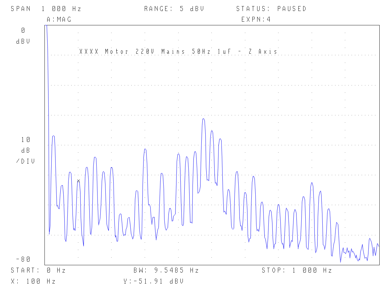
Medium/large sized flywheel rotor synchronous motor 220V (with skewed windings) – at 1500rpm the stored energy is 2.4 Joules, twelve times that of the B112 motor and six thousand times the Philips MB12! The speed variation plots show a very steady constant speed and little sensitivity to the type of supply in terms of maintaining a constant speed. Clearly this is due to the smoothing of the flywheel/rotor. However, the accelerometer plots do show differences depending on the type of drive. I believe this shows that there is real merit in using both measurement approaches – i) the speed should be as constant as possible AND ii) the vibration is affected by the drive. It is also important to note that the torque forces are larger as it is a bigger motor and so the measured torque reaction of the accelerometer is relevant even if the flywheel (and motor mass) absorbs/low pass filters the energy in terms of lack of measured speed variation. In addition we are close to the fundamental limit resolution/noise floor of the speed variation approach. The magnitudes on the accelerometer plots are in the same range as the much smaller Papst B112 which is really impressive given the larger size, however the ‘spiky’/repeated amplitude nature as the spectrum frequency increases does not currently have an explanation other than a link to the Z axis vibration which shows a noticeable 25Hz repeating spectrum – vertical imbalance? 25Hz is related to the rotational frequency and not the drive voltage frequency. I have just proved this out, by resetting the alignment of the thrust pad at the bottom of the motor, it removed this artefact! Measurements were also made at 37Hz (1110rpm) as this would allow 33 & 45 rpm within the 1500rpm design. I have added the 110V 60Hz version of this motor to the tests.
.
.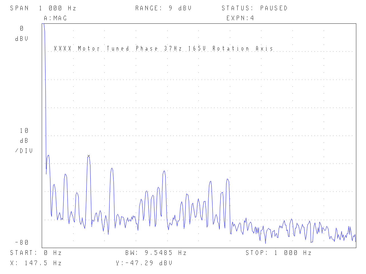
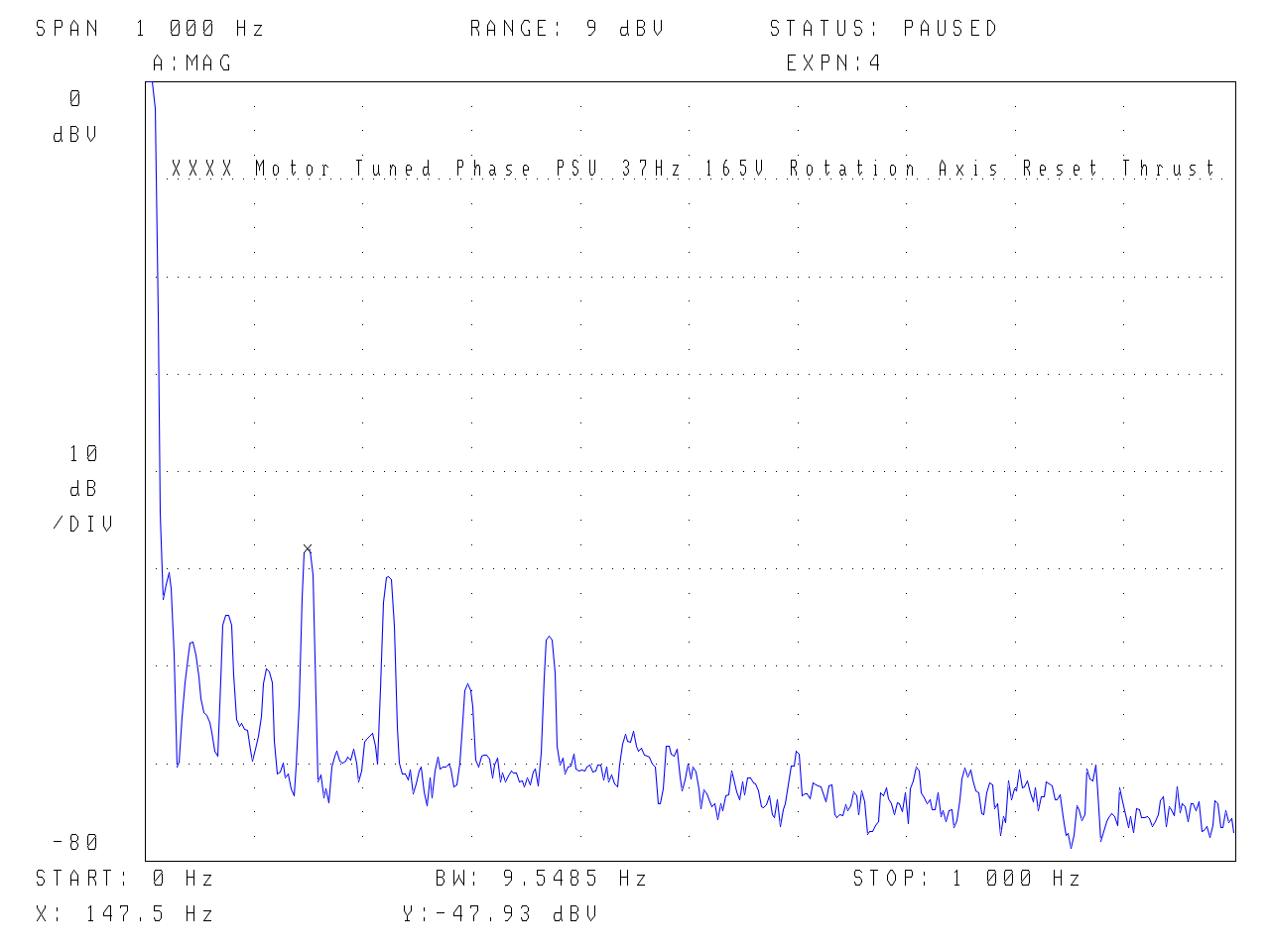
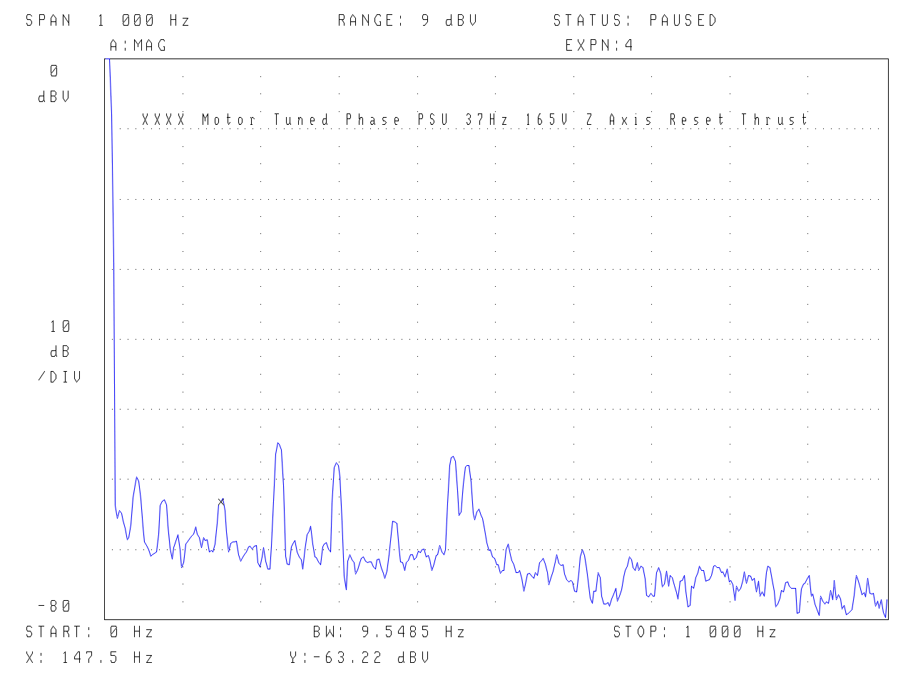
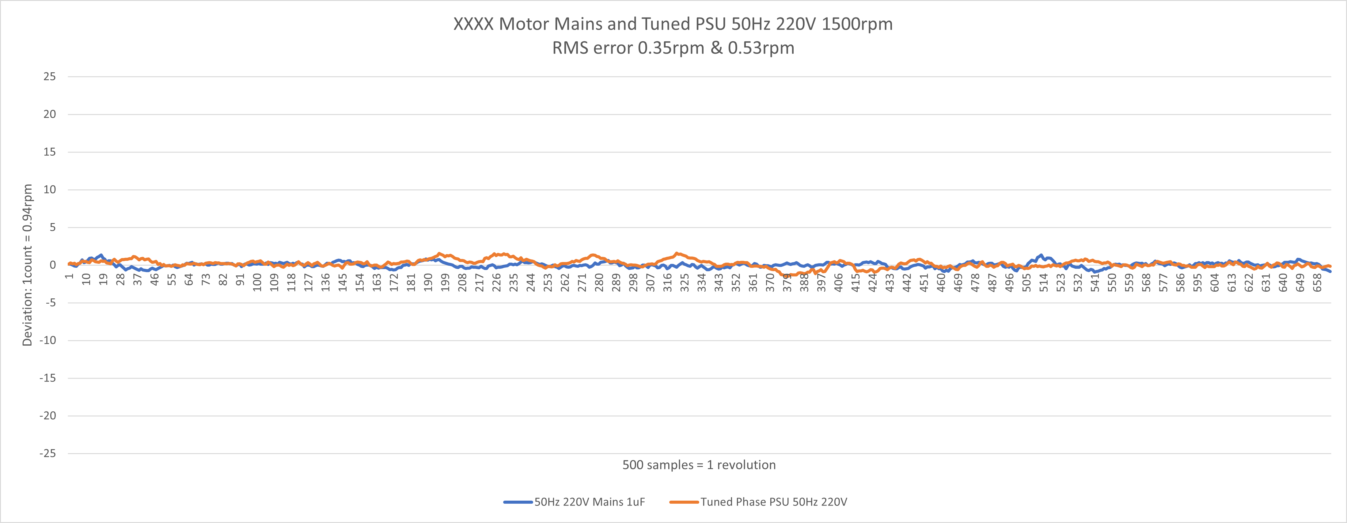
Plot below is the speed variation for 50Hz 220V 1500rpm operation plotted at a similar scale as the B112. The mains fed motor is marginally better however, the variation in the supply frequency/quality as well as the -40dB vibration peak at 100Hz would indicate a dedicated PSU as being overall a better solution.
.
Summary – Lenco GL75 Shaded Pole Motor
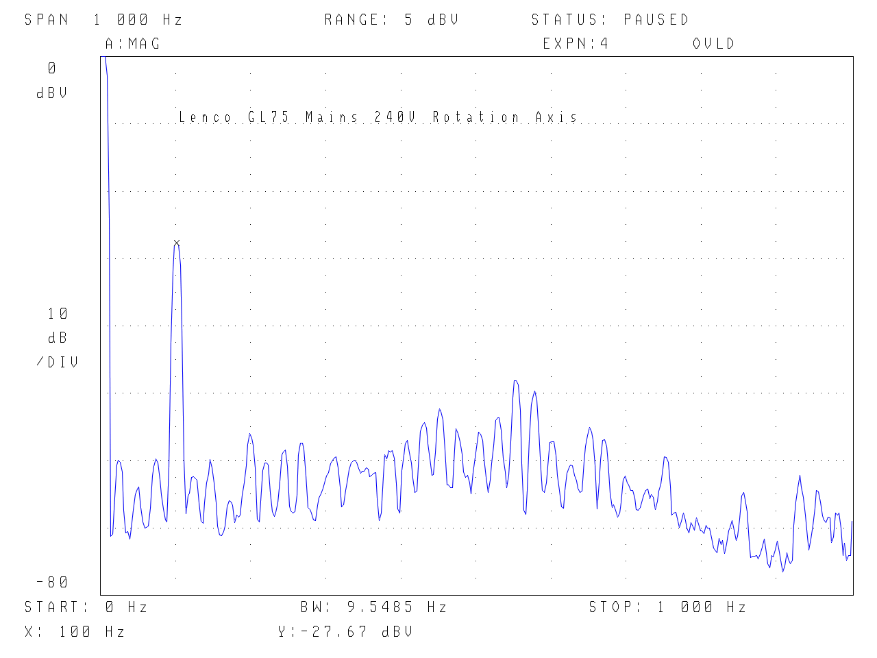
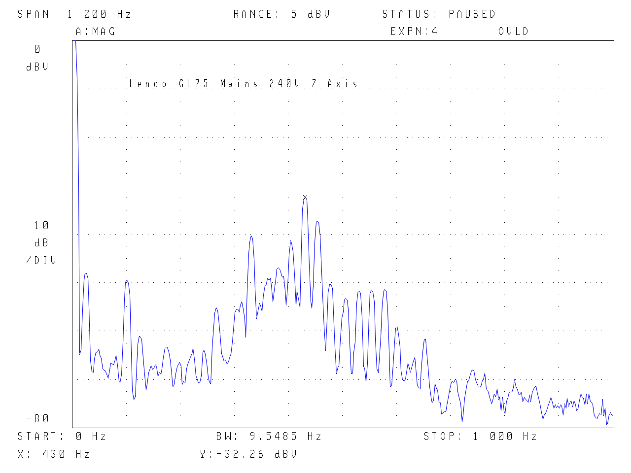
The vibration plot shows a strong vibration at supply voltage frequency. In the rotation axis this is due to the rotor speed variation and as stated above no amount of mass/damping will alter the speed variation. Yes, the vibration caused by this can be damped but the speed is still varying…… It is a nicely balanced motor with moderate stored inertia, however the shaded pole design means there is little that can be done to improve, it is simply an old design with inherent limitations. Reducing the voltage and a clean supply is the limit – a 5 rpm reduction in intra-cycle speed variation is possible which equates to a 3dB reduction in vibration. (When I tested back in 2014 this also revealed these subtle changes depending on the drive but the underlying issue with varying intra-cycle speed is a limitation. Also the amplitudes of the plots from 2014 are larger as the accelerometer was mounter further away from the axis of rotation whereas these measurements are normalised to be able to compare to all the other motors).
.
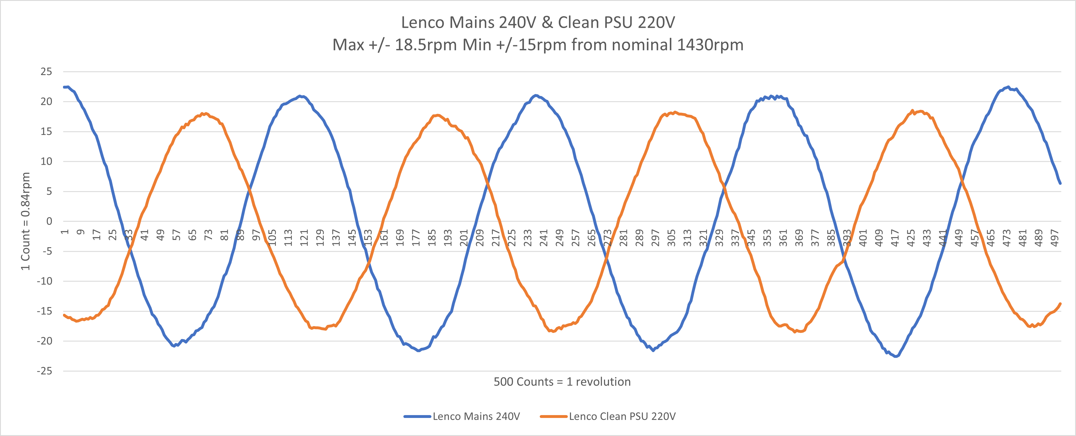
Speed Variation – Note the plots are not synchronised because the motor is not synchronous. The index pulse that triggers the reading is in the same shaft location but the operation of the motor means it is random as to where the motor cycle is at.
.
Motors – follow the embedded links for all the plots…
Philips/Airpax – Ariston, Systemdek, Linn, Rega etc. Torque 10mNm, Inertia = 12gcm, Energy 0.4mJ (250rpm)
Papst HSZ B112 – Voyd, Gyrodek etc… Torque 4.5mNm, Inertia = 173gcm, Energy 0.2J (1500rpm)
Maxon Ironless Brushed – 118743 Torque 29mNm – Various turntables, Inertia = 10.8gcm Energy (est) 13mJ (1500rpm)
XXXX Motor 220V Synchronous Torque 18mNm, Inertia = 1693gcm, Energy 2.1J (1500rpm)
XXXX Motor 110V Synchronous Torque 18mNm, Inertia = 1693gcm, Energy 3J (1800rpm)
Papst HSZ B151 – Voyd Reference Torque 23mNm, Inertia 2117gcm Energy 2.6J (1500rpm) & 0.65J (750rpm)
Crouzet 825400 – Similar to Avid Acutus – Torque 140mNm, Inertia 176gcm, Energy 8mJ (300rpm)
Lenco GL75 Shaded Pole – Torque 10mNm, Inertia 360gcm, Energy 0.4J (1400rpm)
Work in Progress below…
Maxon Ironless Brushless – 351144 Torque 35mNm, – Not a typical turntable motor but I have one..
Ironless PMSM – external rotor Inertia 2384gcm, Energy 2.9J (1500rpm)
NanoTech BLDC – small external rotor
©21C Innovations Ltd 2024
