This is the 110V 60Hz version of the 220V 50Hz type – an exquisite motor – a substantial stored energy of 3 Joules at 1800rpm and super finely balanced with <10 milligram two plane adjustments to the rotor. This is evident with small drill holes – 1.5mm diameter and 1mm deep (or greater) to remove very small amounts of mass.
As the results show this is an amazing motor when optimised….
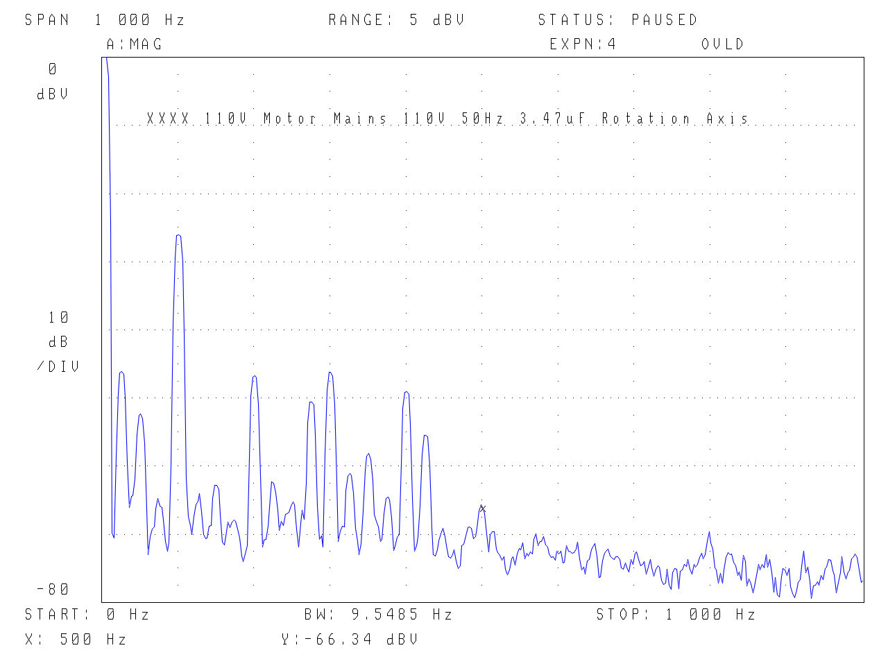
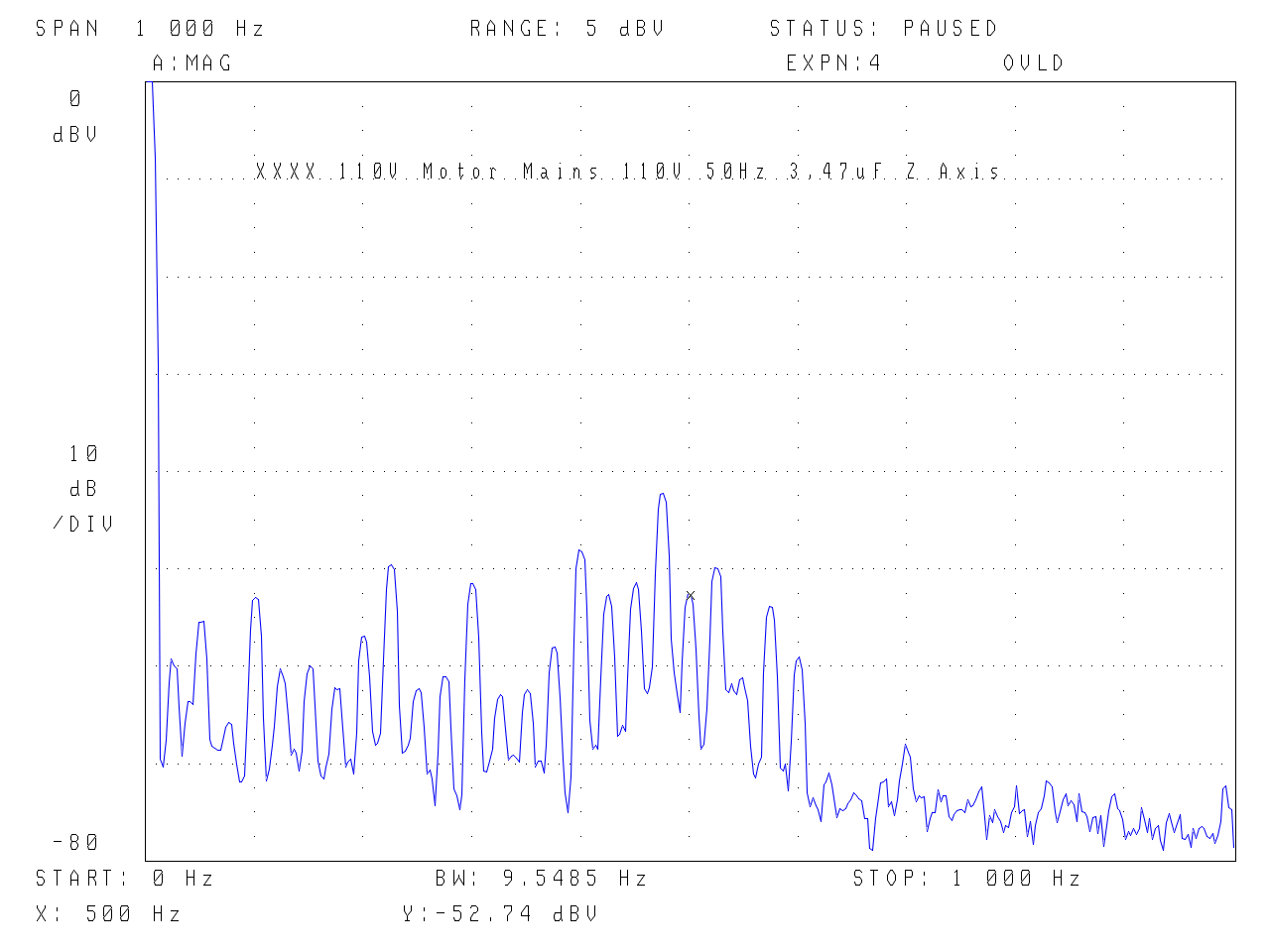
First plots are mains 110V 50Hz with 3.47uF run capacitor. Peaks at 25Hz (rotational speed of rotor) and 100Hz (supply x 2).
.
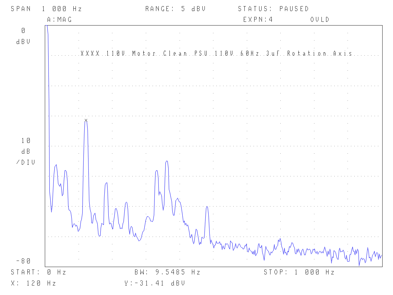
Next are 110V 60Hz from a Clean PSU with 3uF run cap.
.
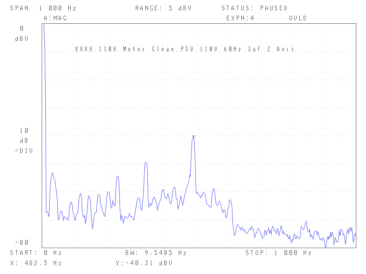
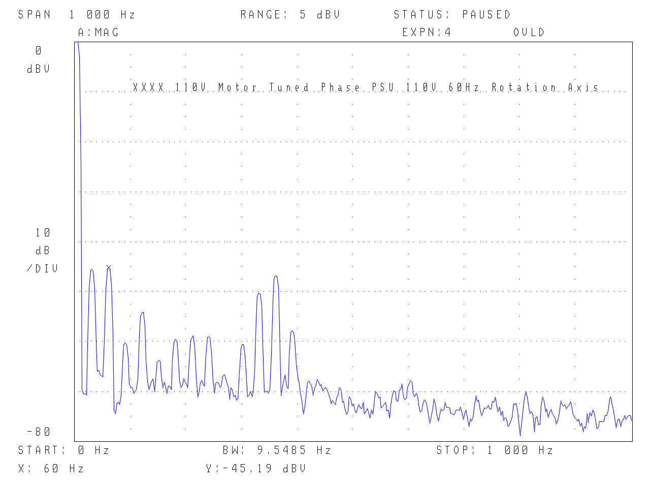
The following are 110V 60Hz from the Tuned Phase PSU.
.
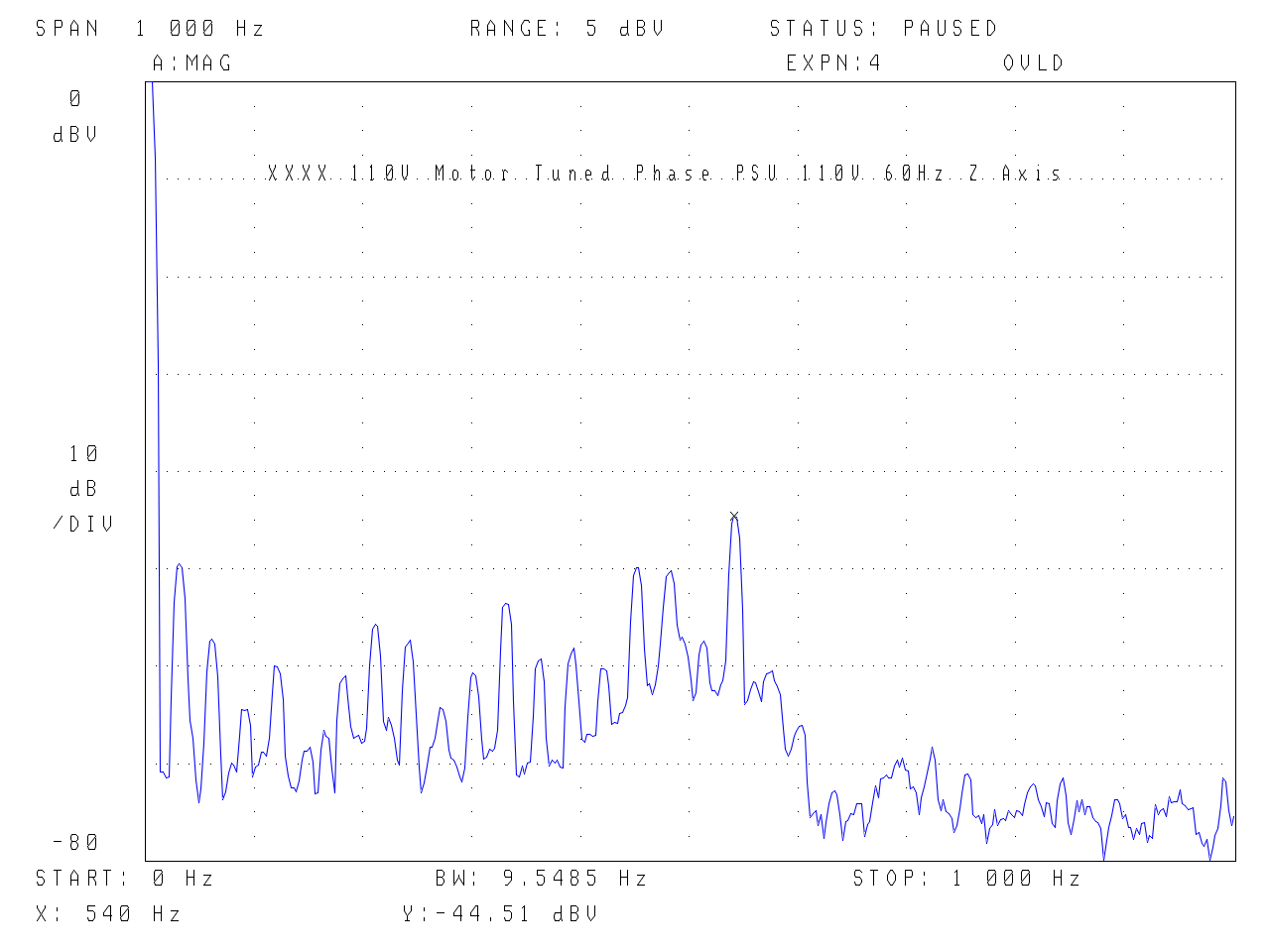
Below are 85V at 44.4Hz (1330rpm) using the Tuned Phase PSU
.
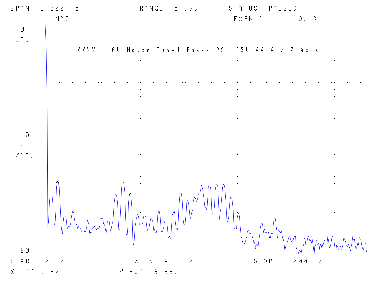
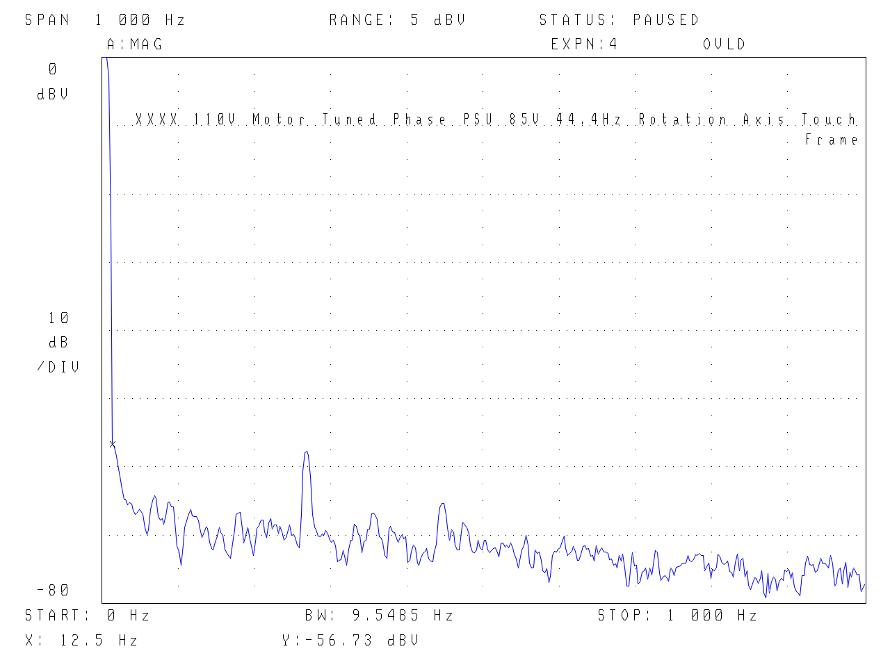
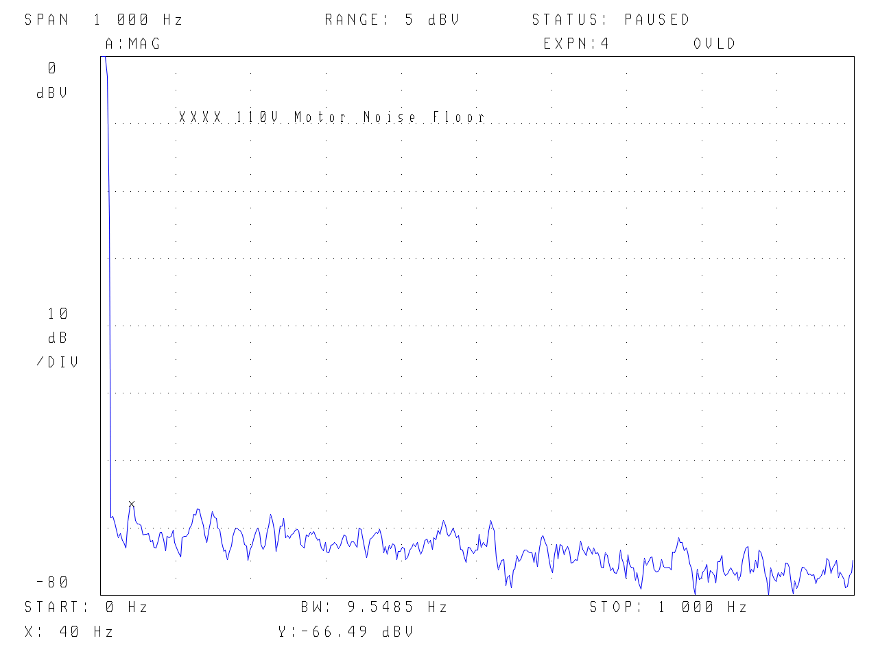
Now the 85V, 44.4Hz operating point with the 3D printed mounting plate touching the frame and the accelerometer noise floor for this measurement session – quite remarkable!
.
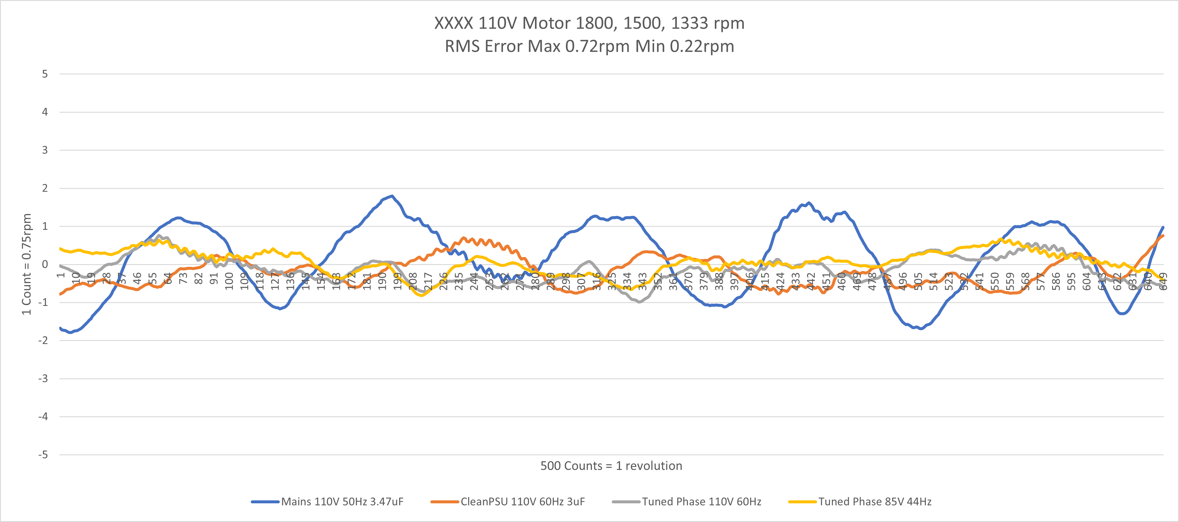
Speed variation – all the different operating speeds are corrected so they can be plotted together. Clearly the tuned phase improves over mains. The residual ‘per cycle’ e.g. 500 count variation is the eccentricity of the code wheel as opposed to the motor speed – the speed variation from the rotating flux is 4 times per rev as the mains plot shows so cannot introduce a one per cycle variation. As mentioned before we are reaching the noise floor/resolution limit of the 50nS clock tick and 500 pulse codewheel, particularly when interpreting data less than 1 count.
.