There are a few aspects of patents that are worth running through first…
Even though an idea/novel solution may well have been conceived independently of visibility/knowledge of similar prior art, if there is relevant prior art (anywhere in the world) it will likely prevent patenting and could also prevent commercialisation. Patent law has evolved over time and in order to function has hard boundaries. It can be a hard pill to swallow as the passion of thinking one has genuinely solved a problem/made something better is challenged by something you were not aware of….. It is tough but it happens all the time.
Identifying the problem to solve is not the invention/innovation – only the novel solution of the problem is recognised as having value.
It is not possible to patent something that already exists for a different reason than the original inventor described. There are numerous examples of this – one example would be car suspension. Inventor A patents the use of a spring & damper to keep the wheels in contact with the ground over bumps/undulations. Inventor B files a patent application for the same configuration for the purpose of ‘comfort’. This would fail as there is no clear novelty over Inventor A’s patent, is structurally the same, just a different tuning of dynamic response and if granted, Inventor B could block Inventor A from minor/subtle adjustments. Another example is there is a patent for a gear covered in gasoline where the gasoline is explicitly mentioned to be used for the lubrication of the gear. It is not possible to patent the same gear covered in gasoline embodiment where gasoline is explicitly used for cooling as it evaporates – there has been no novel invention/innovation, just a different observation of the original patent. A final example would be negative feedback around an amplifier – Inventor A patents the use of negative feedback to reduce distortion, then Inventor B tries to patent the use of negative feedback to reduce DC offsets/drift. It is the same structurally just a different observation of the benefits of the novelty proposed by Inventor A and was already inherently occurring.
Typical process:-
- A novel solution to a problem is developed, 2. Prototype to demonstrate benefit, 3. Engage with patent attorney – Prior art search (patents and public domain) – prior to the internet, the patent attorney would perform the search or possibly recommend this is left to the examiner, but there is a risk with this as it is harder to make adjustments depending on prior art, hence best to search first, 4. Don’t show to anyone unless under a confidentiality agreement – this is difficult, but important if you are serious about licensing…. 5. If all tests (novelty, prior art etc.) are met, patent should be granted, validating potential license agreements/ royalties.
Multi-motor Patents
The first multi-motor, belt drive patent is from VM corporation 1966 ‘VM’
Then there is a patent from Les Wolstenholme in 1985 ‘LW’ which cites the earlier VM patent. (On FB there is what looks like a filing from LW in 1983 (83.21212) but it is not clear if this was dropped, possibly because of prior art search results and it is certainly not cited in the 1985 filing, which if it had any merit, would be… )
Neither of these application were pursued to grant. (Also there was a French turntable from Jacques Marteau, reviewed in 1986 (so most likely existed before) that comprised 4 spindles (driven from 1 motor) with a platter floating on a bed of mercury – nice and safe!)
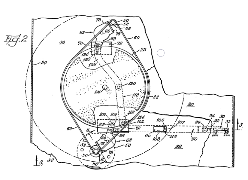
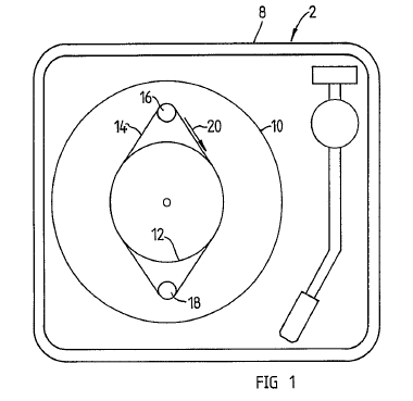
Here are images of the two configurations – left/1st is VM – right/2nd is LW


And here is relevant text from the embodiments.
VM discloses – Pg3 Line 5 “The use of a pair of pulleys so mounted will equalize the side pull on the floating turntable.”
LW discloses – Pg1 Line 68 “There is no recognition on this prior patent however of the need to employ two or more turntable drive motors to reduce or overcome the transient effects of the varying loads under music drive between the record and the stylus;” and the main claim (1) of LW on pg 2 can be paraphrased as ‘A plurality of motors with single diameter pulleys and the motors able to rotate at more than one speed’.
What LW discloses as the potential instability under load was already inherently addressed by the earlier VM embodiment as the geometry/structure is the same. (‘Inherency’ is a patent law doctrine – plenty of info on Google). The removal of the mechanical speed change of the VM patent and replacement with electronic speed change is not novel to a person ‘skilled in the art’ (i.e. ‘normal skills’) in this specific field (turntables) – electronic speed change was already present from the 1970’s with many turntables with DC motors and as well as a few with synchronous motors being readily commercially available. (The Thorens TD125 in the 70’s had an electronic/electrical multi-speed power supply and 24V synchronous motor, Pink Triangle ~1980 had DC motor with speed change, the Linn Valhalla 1982 – had only one speed with a crystal square wave filtered to sine, it would be a no brainer for second crystal/speed…..)
The later LW filing is thus structurally very similar with a different observation of benefit of the original VM idea, which meant it was unlikely to be granted due to inherency and probably explains why it was not progressed. This also means that any potential license based on the assurance from LW of a valid patent would fail – just filing a patent application does not validate the innovation. To then pursue royalties with a failed patent would be commercially unsupportable – why would someone pay a royalty when the person next to him did not have to? The next step would have been to negotiate if a license ‘for use of the technology’ was relevant, however, the tests for this still typically require a novelty test based on a potentially valid draft patent application, or equivalent, again in order to ensure commercial validity. This would then leave commercialisation by LW as the option.
In summary, since shortly after 1966 when the VM patent was dropped, multi-motor belt drive turntables were free to develop, contrary to what LW believes and what a formal ‘legal opinion’ determination found.
I to V DAC Patent – click here for the pdf
This was my first patent. It came about after talking with Peter Qvortrup of Audio Note UK in 1993 about how, at the time, all high end audio DAC’s used a ‘cookbook’ circuit where the output of the DAC integrated circuit(s) were fed into op-amp(s). So the problem statement was ‘how can we replace the op-amps to work with a passive + tube based solution’.
The current (I) output of typical R2R ladder DAC IC’s is relatively high impedance (670 ohms for the BB PCM63P) and were typically fed into the virtual earth (negative) input of an op-amp, thus operating at essentially 0 volts. Was it feasible to provide a sufficiently low impedance stage to accurately convert the current and not adversely affect the designed/intended operating range of the current output? The solution was to use a low impedance transformer directly on the output of the DAC which would offer about a 100ohm dynamic load as well as potentially separating grounds*. This could then be followed by a passive multi stage L-C antialiasing filter and tube gain stage. It worked a treat and a patent application was filed. This did meet an ‘obviousness’ challenge from the examiner as it was seen as a combination of audio components (DAC IC’s, transformers) and RF filters. Our attorney’s response was that if it was obvious to someone skilled in the art why had it not already been done and also the person skilled in the art needed to cover both the domain of high end audio design and RF. The patent was subsequently granted. I transferred ownership of the patent to Peter for him to use and license and even though the patent has expired, this seems to still be a valid active area of development. (BTW the term person ‘skilled in the art’ is someone who has ‘normal’ skills in a ‘particular field’, not a genius….)
*The PCM63P DAC IC has a potential voltage swing across it’s internal impedance of +/-1.34V. Adding the external 100 load would increase this by +/-0.2V so, in order to mitigate potential internal transistor biasing changes of the effective swing now being +/-1.54V, the nominal +/-5.0V power supplies can be increased to +/-5.2V which is still well within the maximum limit of +/-5.5V. Obviously this correction is dependent on the internal circuit topography.
©21C Innovations Ltd 2024
